Audio Latency Examiner
06 Aug 2024
•
audio
•
latency
•
software
•
realtime
...
As a teacher and enthusiast of networked music, latency in musical devices is something I care about. However, whenever I've run latency measurements of audio systems in class or in the field, I've always missed specialized software capable of administering measurement impulses and collecting large amounts of data, all in one. In light of this, I recently designed a small software tool for measuring and batch-collecting audio latency data from musical software and hardware devices, called Audio Latency Examiner (ALEX). The goal of ALEX is to provide an easy-to-use, lightweight and intuitive software (for non-software engineers) that still retains enough advanced functionality to enable precise, scientific, and methodical latency measurement practices.
In this post, I document how ALEX works and explain some of its main features and design concepts. At the bottom, find relevant links to download the software and report any issues you might have experienced.
How It Works and How To Use It
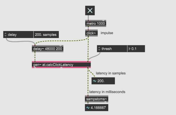
ALEX collects latency data in real-time by evaluating the arrival time differences between audio impulses (click~) that the software itself administers. One impulse travels out and through the device you wish to measure, while the other acts as a reference, providing the same initial conditions to the reference and delayed signal chains. In particular, the latency is calculated by having the reference impulse start a sample-based counting process that the delayed impulse stops. The amount of counted samples is equal to the latency between the two signals.
However, with this particular measurement strategy, it's extra important for users to ensure that the device or VST they wish to measure is not bypassed in any way. For instance, when dealing with a VST, set the "Dry/wet" parameter to 100% wet before measuring. The software requires the audio impulses to be fully processed by the effect to generate valid data. When bypassed, the signal paths inside the devices may differ, resulting in bad results.
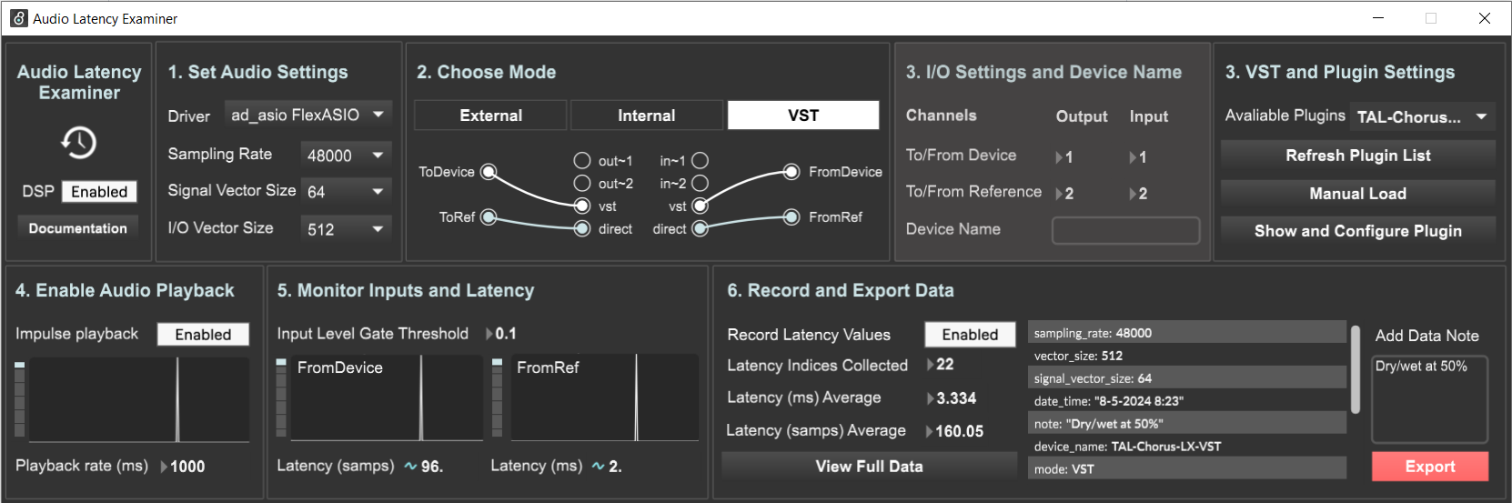
When using ALEX, first set the correct audio and device settings, enable DSP, and choose the correct Mode. Then, start the audio playback. The audio playback engine plays the audio impulse in a sequence on repeat, at a rate defined by the "playback rate (ms)" parameter. The playback rate number determines the time separating each click sound in the sequence. Finally, monitor the input signals to ensure the audio impulses are clean and stable and start the data collection. When you're happy with the data you've collected, export the data locally via the "export" button.
Modes
To accommodate a majority of both software and hardware devices, ALEX provides the option to choose between different measurement modes. The Modes are essentially routing schemes, deciding where to send and receive the delayed and reference audio impulses. The device input and output channels, sometimes labeled as toDevice and fromDevice, should always go to and from the measurement object, while the reference channels, sometimes labeled toRef and fromRef, should always be the reference chain.
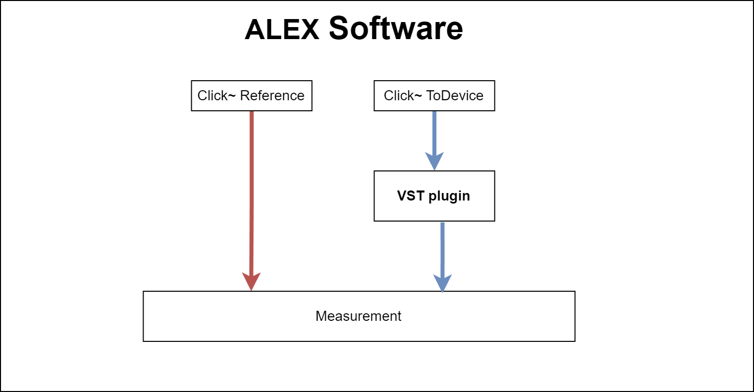
Upon choosing a mode, the dedicated audio and channel routing are made visible in the patch area. For instance, in the VST mode, the toDevice signal path goes to and from the VST specified in the "VST and Plugin Settings" section, while the reference passes directly to the measurement inside the software. It's not possible to edit the patch area, but you can select the out~ and in~ channels needed for the External and Internal modes from the "I/O and Device Settings" section.
Below are more detailed accounts of the intended use of the different measurement modes. It should be said that these modes and uses are just templates and simple guidelines. Feel free to use them in any capacity you like.
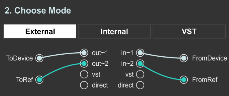
External Mode
Use the external device mode to measure the roundtrip latency of any external musical device, such as delay pedals, networked systems, analog instruments, etc. To get the best results, the routing of the external mode is designed in a a loopback fashion, sending both reference and device impulses out of the computer (to the target device) and expecting to receive the same signals in return. Therefore, using this mode requires the use an external audio interface with two or more inputs and outputs.
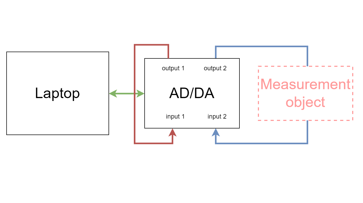
To be able to send audio out and in from your laptop, remember to specify the correct audio driver from the "Audio Settings" section and set the correct channels under the "I/O Settings and Device Name" section.
Internal Mode
Use the internal device mode to measure the roundtrip latency of any internal audio device, such as virtual audio drivers, analysis software or audio units. The routing of the internal mode is designed similarly to the external mode, but sends only one impulse out of the assigned audio driver to a designated audio device, expecting to receive the same signal in return as input. The reference signal in the internal mode is passed directly within the software, not leaving the Max8 environment.
When using the internal mode, you need to set your audio driver to a virtual audio driver to be able to send the signal to another software. This can be specified in driver settings under the "Audio Settings" section. Also, set the correct channels to send/receive the device signals under the "I/O Settings and Device Name" section.
VST Mode
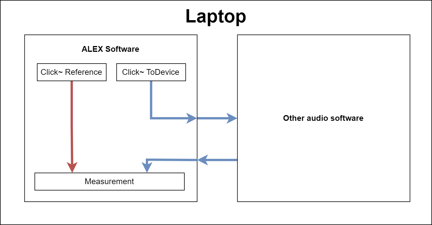
Use the VST mode to measure the latency of any VST plugin installed on your machine. The VST mode sends an impulse to the VST and compares the output to a direct signal (reference) that does not pass through the VST.
When using the VST mode, you must configure the plugin settings manually via the "Show and Configure Plugin" button under the "VST and Plugin Settings" section. Also, since the data does not store the parameter settings of the VST, remember to add notes about the parameters used in the "Add Data Note" section under the "Record and Export Data" header.
Monitor Inputs and Latency
You can view the latency of your device via the number boxes under the oscillator scopes in the "Monitor Inputs and Latency" section. These latency numbers represent the time difference between the incoming reference and delayed audio impulses in samples and in miliseconds. However, to get reliable results, it's important to tend to the input level gate threshold parameter.
Input Level Gate Threshold
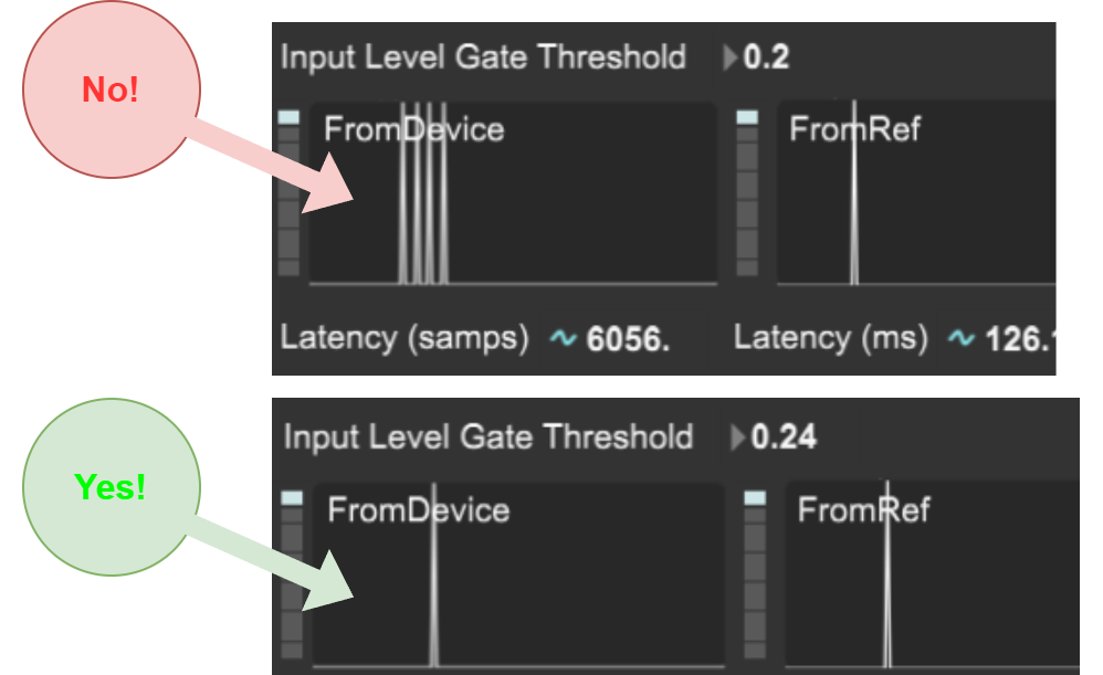
When passing through analog hardware or delay plugins, the audio impulses administered by ALEX can sometimes get noisy and distorted. However, when evaluating the time difference between the audio impulses, the software relies on stable and clean clicks to be able to make accurate predictions.
The "Input Level Gate Threshold" is essentially a noise gate that filters out input signals where the normalized amplitude values are less than the value specified in the number box. So, by increasing the "Input Level Gate Threshold" you can achieve better signal-to-noise ratios on the input signals for better data. It's best to tune this parameter in real-time while monitoring the input signal in the scope. Increasing the value too much will result in no input at all.
Last, it should be said that the reference and delayed impulses are subject to this exact same filtering chain before being evaluated.
Record and Export Data
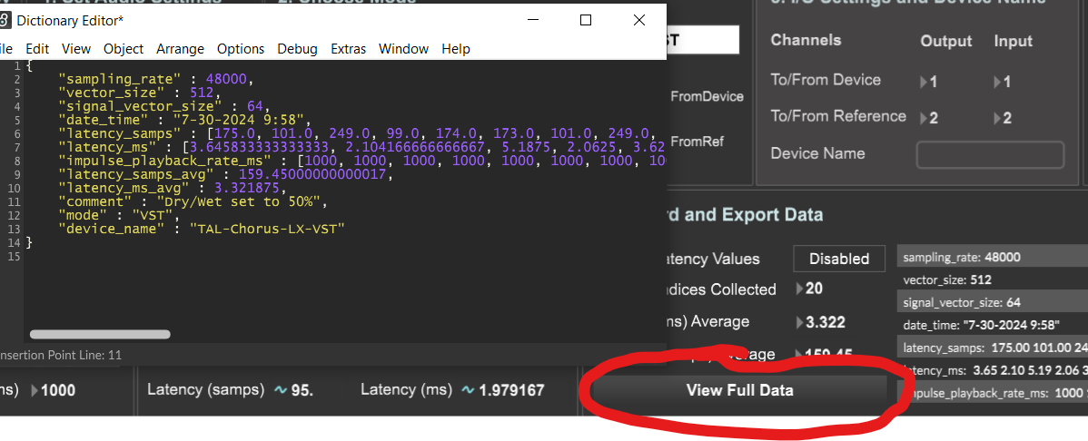
The software collects latency and device data into a dictionary (JSON) format. Specifically, the latency metrics are float numbers collected into separate arrays in the dictionary. You can click the "View Full Data" button to inspect the entire data structure and even make custom changes if needed.
Here is a complete list of data points collected by ALEX:
- device_name = (string) the name of the musical device whose latency you are measuring.
- mode = (string) measurement routing mode
- data_time = (string) the current time when the data collection process was enabled.
- sampling_rate = (int) the current sampling rate of the chosen audio driver
- vector_size = (int) the current vector size (sometimes called buffer size) of the chosen audio driver.
- signal_vector_size = (int) the current Max signal vector size (sometimes called audio block size).
- latency_samps = (array) a collection of the device latency in samples.
- latency_samps_avg = (float) the number average of the latency_ms array
- latency_ms = (array) a collection of the device latency in milliseconds.
- latency_ms_avg = (float) the number average of the latency_ms array
- impulse_playback_rate_ms = (array) a list of the audio impulse playback rate used during the collection process.
- note = (string) the personal comment you can add to the data specifying details about the measurement process or device used.
The data-gathering procedure can be commenced at any time, given that the DSP and Audio Playback processes are enabled beforehand. After collection, the data can be exported as a JSON format object for easy post-analysis and documentation.
Download Link and Report Issues
ALEX is free and open-source, available as a standalone desktop application for both Windows and Mac. You do not need a Max license or Max installed. Download the latest version of ALEX on this GitHub page. Also, I encourage you to report any issues you experience while using the software on the same GitHub page.
ALEX builds on the code examples from Graham Wakefield on batch-collecting audio latency data in MaxMSP (read more on the Cycling '74 forum.) and is inspired by my time as a teacher for several networked music courses at UiO.